Theory of LED Dot Matrix Display
In a dot matrix display, multiple LEDs are wired together in rows and columns. This is done to minimize the number of pins required to drive them. For example, an 8×8 matrix of LEDs (shown below) would need 64 I/O pins, one for each LED pixel. By wiring all the anodes together in rows (R1 through R8), and cathodes in columns (C1 through C8), the required number of I/O pins is reduced to 16.
Each LED is addressed by its row and column number. In the figure below, if R4 is pulled high and C3 is pulled low, the LED in the fourth row and the third column will be turned on. Characters can be displayed by fast scanning of either rows or columns. This tutorial will discuss the method of column scanning.
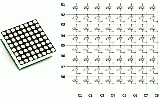
Structure of an 8×8 LED Dot Matrix
The LED matrix used in this experiment is of size 5×7. We will learn how to display still characters in a standard 5×7 pixel format. The figure below shows which LEDs are to be turned on to display the English alphabet ‘A’. The 7 rows and 5 columns are controlled through the microcontroller pins. Now, let us see in detail how it works.
Suppose, we want to display the alphabet A. We will first select column C1 (which means C1 is pulled low in this case), and deselect other columns by blocking their ground paths (one way of doing that is by pulling C2 through C5 pins to logic high).
Now, the first column is active, and you need to turn on the LEDs in rows R2 through R7 of this column, which can be done by applying forward bias voltages to these rows. Next, select the column C2 (and deselect all other columns), and apply forward bias to R1 and R5, and so on. Therefore, by scanning across the column quickly (> 100 times per second), and turning on the respective LEDs in each row of that column, the persistence of vision comes into play, and we perceive the display image as still.
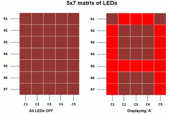
A standard 5×7 LED dot matrix display structure
How LED Matrix are operated
The table below gives the logic levels to be applied to R1 through R7 for each of the columns to display the alphabet ‘A’.
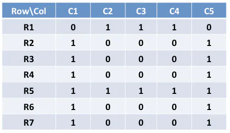
Row values of each column for displaying the alphabet A
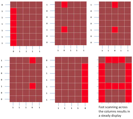
Scanning across the columns and feeding with appropriate row values
You should have noted that across each row, one pin is sourcing the current for only one LED at a time, but a column pin may have to sink the currents from more than one LED. For example, column C1 should be able to sink the currents from 6 LEDs while displaying the alphabet ‘A.’
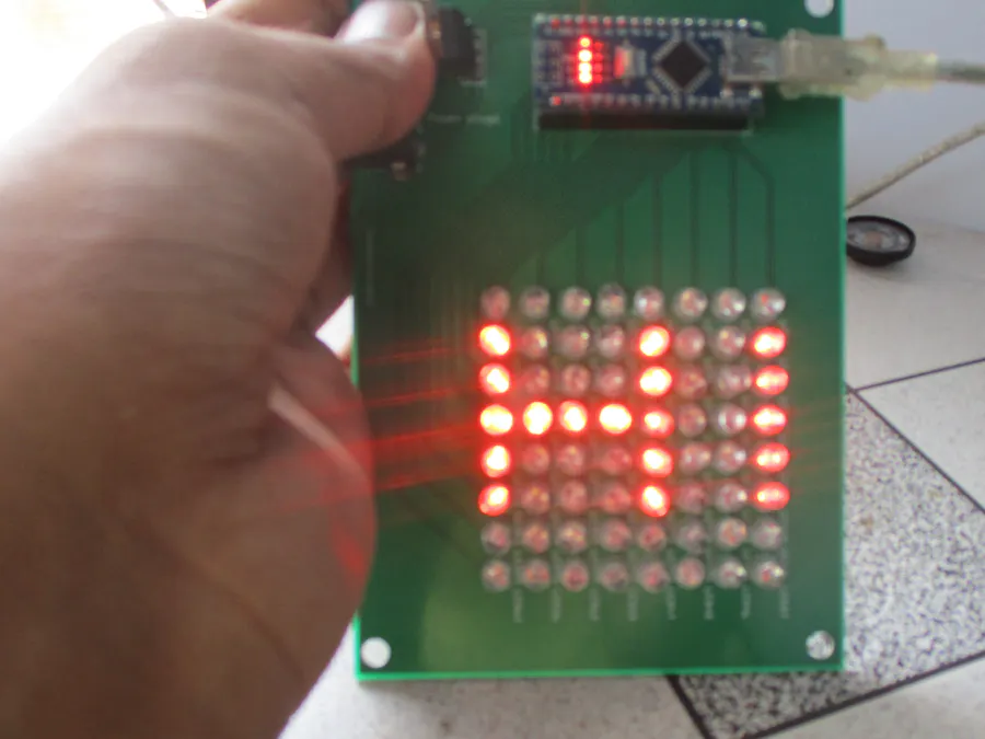
Then I decided to make my own LED Matrix so I started working on it.
You will need an Arduino Nano for this. if you do not know how to program an Arduino then go to this link https://robocircuits.com/index.php/2024/06/13/how-to-setup-arduino-ide/
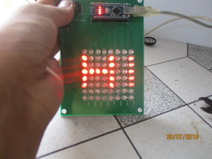
So I tried to make one of my LED matrices.
I took 64 RED LEDs and designed a printed circuit board from Fritzing.
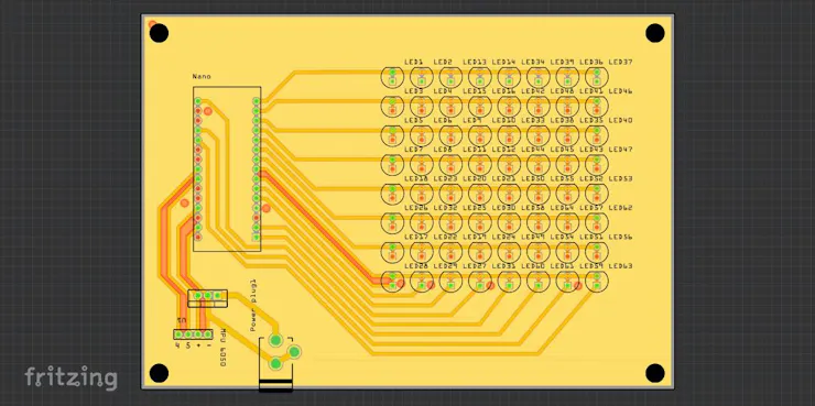
Then I ordered the board from a professional manufacturer JLCPCB. Which are the top PCB manufacturers in China. They provide the cheapest and best quality boards which get ready only in 2 days.
After I soldered all the parts, my project was done.
Code
//RoboCircuits
//Youtbe www.youtube.com/robocircuits
//Website http://robocircuits.com
//Please Subscribe us and share this tutorial
byte H[] = {
B00000000,
B10001001,
B10001001,
B11111001,
B10001001,
B10001001,
B00000000,
B00000000};
byte R[] = {
B11111100,
B10000010,
B10000001,
B10000010,
B11111100,
B10010000,
B10001000,
B10000010};
byte S[] = {
B01111111,
B10000000,
B10000000,
B10000000,
B00000000,
B10000000,
B10000000,
B01111111};
byte R[] = {
B11111100,
B10000010,
B10000001,
B10000010,
B11111100,
B10000100,
B10000010,
B10000001};
byte C[] = {
B00111111,
B01000000,
B10000000,
B10000000,
B10000000,
B10000000,
B01000000,
B00111111};
byte random1[] = {
B01010101,
B10101010,
B01010101,
B10101010,
B01010101,
B10101010,
B01010101,
B10101010};
byte random2[] = {
B10101010,
B01010101,
B10101010,
B01010101,
B10101010,
B01010101,
B10101010,
B01010101};
const int columnPins[] = { 12, 11, 10, 9, 8, 7, 6, 5};
const int rowPins[] = { 4, 3, 2, 0, 1, 13, 14, 15};
void setup() {
for (int i = 0; i < 8; i++)
{
pinMode(rowPins[i], OUTPUT); // make all the LED pins outputs
pinMode(columnPins[i], OUTPUT);
digitalWrite(columnPins[i], HIGH); // disconnect column pins from Ground
}
}
void loop()
{
int Delay = 800 ;
randomeffect();
show(H, 1000);
randomeffect();
show(R, 1000);
randomeffect();
show(C, 1000);
randomeffect();
show(H, 1000);
randomeffect();
show(R, 1000);
randomeffect();
show(C, 1000);
randomeffect();
show(H, 1000);
randomeffect();
show(R, 1000);
randomeffect();
show(C, 1000);
delay(Delay);
}
void randomeffect()
{
for(int a=0;a<2;a++)
{
show(random1,30);
delay(40);
show(random2,30);
delay(40);
}
}
void show( byte * image, unsigned long duration)
{
unsigned long start = millis();
while (start + duration > millis())
{
for(int row = 0; row < 8; row++)
{
digitalWrite(rowPins[row], HIGH); // connect row to +5 volts
for(int column = 0; column < 8; column++)
{
boolean pixel = bitRead(image[row],column);
if(pixel == 1)
{
digitalWrite(columnPins[column], LOW); // connect column to Gnd
}
delayMicroseconds(300); // a small delay for each LED
digitalWrite(columnPins[column], HIGH); // disconnect column from Gnd
}
digitalWrite(rowPins[row], LOW); // disconnect LEDs
}
}
}
Now enjoy!
Visit Our Other Social Media Pages
Facebook – https://fb.com/RoboCircuits
Instagram – https://Instagram.com/RoboCircuits
Twitter – https://Twitter.com/robocircuits