It’s not only a quadcopter… it’s an open-source machine!
Many of you face a problem when it comes to Flight Controller which is the brain of the Multirotor. There are plenty of ready-made pre-flashed Flight controllers in the market for cheap, But have you thought of building your Flight controller with your Arduino? So this is the right place to understand and build your Flight controller for your Quadcopter or Multirotor with your Arduino.
Now the questions come, where and how do I get the code for the quadcopter? So the answer is Multiwii.
MultiWii is a top-rated flight controller software for DIY multi-rotors with a large community. It supports various multi-copters with advanced features such as Bluetooth control by your smartphone, OLED display, barometer, magnetometer, GPS position hold and return to home, LED strips, and many more. So let’s build our flight controller using Arduino!
Step 1: Flight Controller Designing
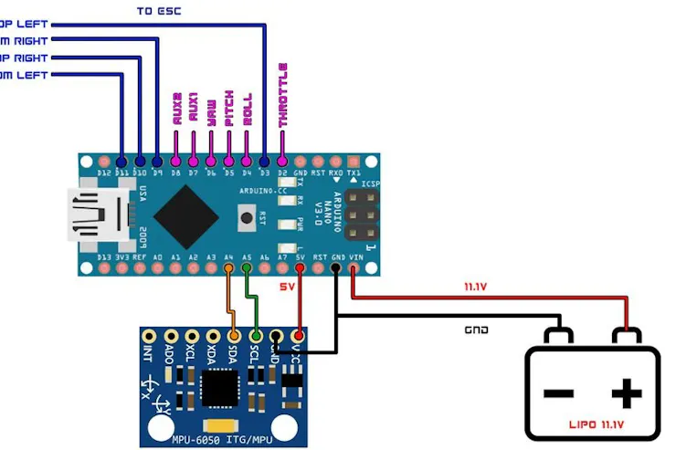
Here are the Schematics for the flight controller board. you can make one on your general-purpose PCB or can Order a PCB from the manufacturer as I did.
ESC Connections
- D3 << ESC 1 Signal Pin
- D9 << ESC 3 Signal Pin
- D10 << ESC 2 Signal Pin
- D11 << ESC 4 Signal Pin
Bluetooth Module Connections
- TX << RX
- RX << TX
MPU-6050 Connections
- A4 << SDA
- A5 << SCL
LED Indicator
- D8 << Anode Leg of LED
Receiver Connections
- D2 << Throttle
- D4 << Elerons
- D5 << Ailerons
- D6 << Rudder
- D7 << AUX 1
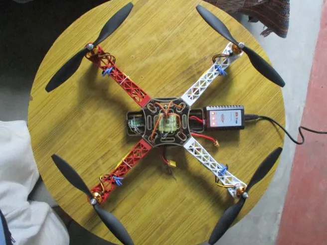
Step 2: Building a Frame
I bought a DJI 450 frame and attached my motors and everything. You can see the video on how I did it.
Watch this video to understand the whole concept
Step 3: Attaching the Flight Controller To the Frame
Then finally attach the ESC and receiver onto the board as shown in the schematics and everything is done!
Step 4: Setting Up the Controllers Multiwii Code
MultiWii’s code is free and easy to use, and it supports many (most) builds.
- Download Multiwii and the Arduino IDE.
If you do not know how to set Arduino IDE click the following link.
- Connect the flight controller to your computer.
- On the computer, open the already downloaded MultiWii folder and open the Arduino file called “MultiWii.ino”.
- Access the tab “config.h” and delete the “//”, selecting the desired type of multirotor.
- Scroll down and enter the minimum and maximum values of your transmitter.
- Uncomment the sensors used.
- Next, follow the instructions commented on throughout the file.
- After that, on the top menu of the IDE, click on Tools, Boards, and select the Arduino microcontroller you’re using.
- Then, click on Tools, Port, and select the computer’s port that your controller is on.
- Upload the Multiwii code by clicking the button shaped like an arrow.
- After uploading, the text “uploaded successfully” should appear on IDE.
Step 5: Using the Multiwii GUI

Open your MultiWii folder, and click on the MultiwiiConf, application.windows32 (or the desired operating system’s option), and finally open MultiWiiConf.exe.
On the top left of the window, select the port your flight controller is on and click on start. Sensor Values should show on the application.
On the right, select the sensor type. To calibrate the sensor, slowly move/tilt the flight controller as prompted.
A model of the desired drone should appear on the application. Its movements should mimic the movements of the flight controller.
Step 6: PID Tuning and Calibration Tips
Connect the flight controller to the multirotor to adjust PID values.
Set the PID values to default and ensure the multirotor’s center of gravity is in the center.
Carefully hold the multicopter so that your gyroscope’s readings in the GUI are flat. Then set the throttle to 50%.
Note: If the accelerometer’s readings fluctuate exceedingly, that is an indication of excess vibration. Vibration dampeners may be required to reduce vibrations (I used Double Sided Tape as an alternative solution).
Now while carefully holding your rotor in a safe place, increase the throttle until the multirotor feels weightless.
Put pressure (lean) on each axis of the drone. You should feel resistance against that change. Change the P value until this resistance is notable.
With your hand, oscillate (tilt) the drone back and forth with your hand. On the application, increase the P value until the drone barely starts oscillating on its own. Now reduce the P value a bit. Repeat this process, this time oscillating the drone to the sides (to the left and right).
The calibrated values should be suitable for flight now.
Step 7: Fly!
Feel free to further experiment with the PID values with caution.
If you think this project deserves it, don’t forget to vote, favorite, or subscribe.
Feel free to discuss other possible features, ask me a question, or share your thoughts in the comment section below.
Have fun flying!